 Survey & CAD
Availability on enquiry
GISMappers Survey Automation
Field-to-finish survey automation for GNSS, total station, linework, terrain models, contours and CAD/GIS export.
SurveyGNSSTotal StationCAD/GIS
View product 
Survey automation software for CAD, GIS, surfaces, alignments, quantities, and final deliverables.
Available for demonstration — release status, licensing and system requirements confirmed on enquiry
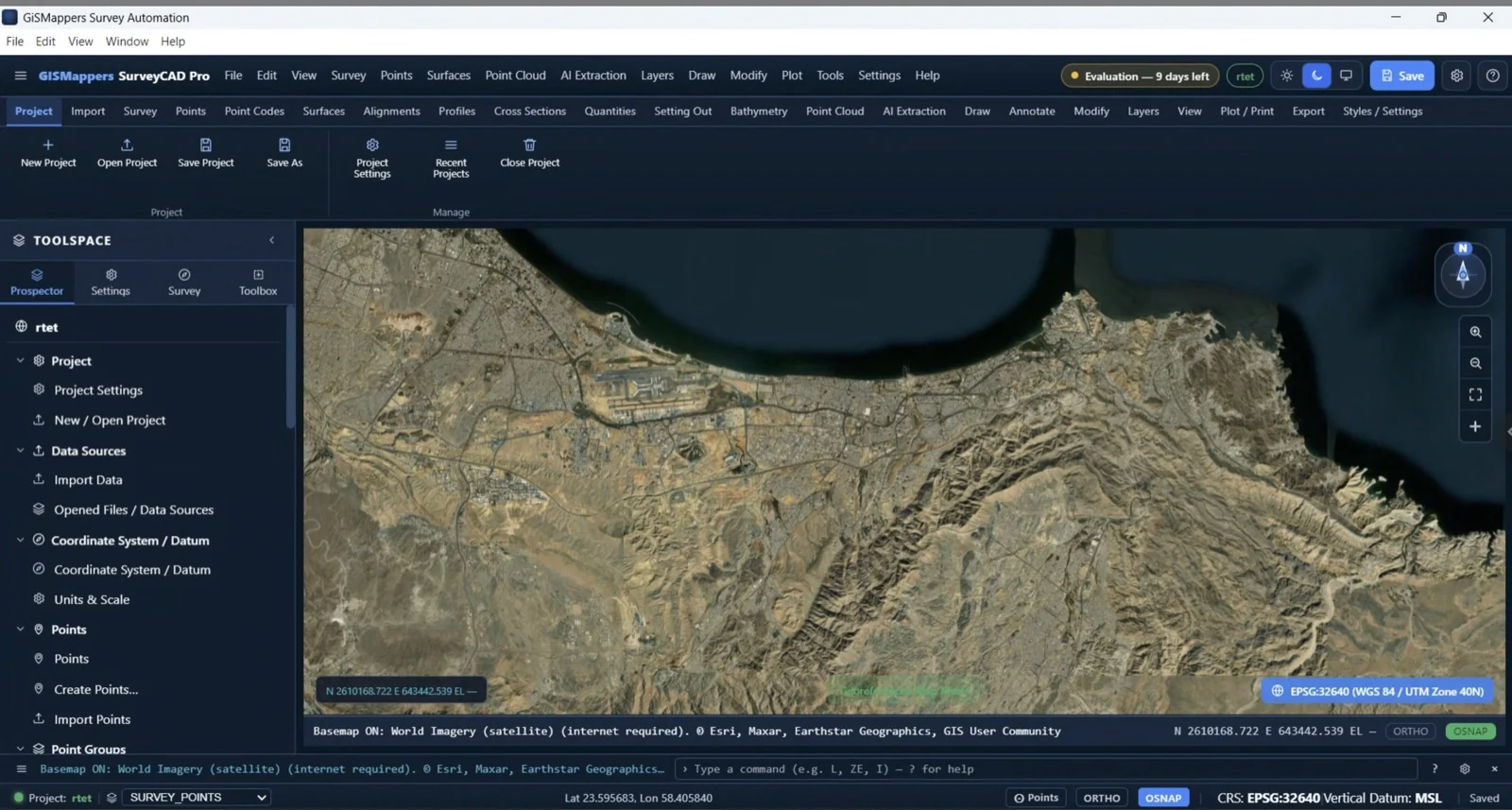
SurveyCAD Pro is a survey automation platform built for field-to-office workflows. It helps survey teams import field data, organise point codes, draft CAD linework, build surfaces and contours, create alignments and profiles, calculate quantities, and export client-ready deliverables.
SurveyCAD Pro is designed to bring survey processing, CAD drafting, surface modelling and deliverable production into a single, structured workflow — so teams can move from raw points to issued drawings with fewer manual steps.
Deliver a field-to-finish workflow from survey data through drafting, terrain modelling and final deliverable production.
Combine CAD drafting, GIS data handling, point cloud support and topographic output workflows in one platform.
Help survey teams produce dependable drawings, models and structured geospatial outputs more efficiently.

Import survey points
Bring in field data from CSV, TXT and PENZD point files.
Point code styles & symbols
Apply code libraries, symbols and labels automatically.
Draft topographic drawings
Build linework, boundaries and detail in a CAD environment.
Build TIN / DTM surfaces
Create triangulated terrain models from survey points.
Generate contours
Major and minor contours with labelling and spot levels.
Raster / DEM / ASC / GeoTIFF
Import elevation rasters and georeferenced background data.
Point-cloud-style datasets
Handle large terrain datasets with level-of-detail display.
Alignments & profiles
Road, rail and utility alignments with longitudinal profiles.
Cross sections & quantities
Section generation and cut/fill volume calculation.
Export deliverables
PDF, DXF, CSV, GeoJSON and structured reports.
Built-in QA checks
Validate levels, duplicates and linework before issue.
Layouts & title blocks
A0–A4 sheet layouts with scale and text control.
SurveyCAD Pro is organised into focused engines. Each engine handles one stage of the survey workflow and is designed to pass clean data to the next.
Set standards before any data is imported
A project begins here. Teams create a new project, choose working units, drawing scale and default text size, then set the coordinate reference system together with horizontal and vertical datums. A default metre unit can be selected so that everything that follows shares the same framework. Setting these standards before importing data helps keep drawings consistent and reduces rework later in the project.
Import, organise and validate field data
Field data is imported from PENZD, CSV and TXT files, each point carrying a number, easting, northing, elevation and description. A configurable point code library assigns symbols and labels automatically, and duplicate-point and missing-elevation checks help catch problems early. Separate style libraries can be prepared for topographic, road, utility and bathymetry work so the right symbology is applied to each survey type.
Familiar drafting tools for survey teams
The drafting environment supports lines, polylines, polygons, circles and text, with editing tools including trim, extend, offset and fillet. Linework can be broken at a single point or between two points, lines can be joined, and properties matched between objects. A layer manager, line styles and CAD symbols keep drawings organised, and a command-panel style of input supports fast, keyboard-driven drafting for experienced users.
Turn points into terrain models
Survey points are triangulated into a TIN / DTM surface, and surfaces can also be built from point cloud, ASC or DEM data. Boundaries and breaklines refine the model, after which major and minor contours can be generated and labelled. Slope display and spot levels add context, and surface quality checks help identify gaps or spikes before the model is used downstream.
Large elevation datasets, handled smoothly
GeoTIFF, ESRI ASC, DEM and raster elevation data can be imported as part of a project. During large imports a progress bar shows live percentage and the import modal stays visible until loading completes, so it is clear the process is still running. Very large point clouds use a level-of-detail display: dots are shown first for performance, and labels are revealed only when the view is zoomed in.
Design centrelines and ground profiles
An alignment can be created from a line or polyline, with chainage / stationing applied along its length. Horizontal alignments support setting-out coordinate generation, while a longitudinal ground profile can be extracted from a surface. Vertical alignments add design levels, with support for crest and sag vertical curves, and profile sheet styles help present the result clearly.
Compare surfaces and measure volumes
Cross sections are generated along an alignment, comparing existing ground against a design surface. From this comparison, cut and fill volumes are calculated and quantity reports exported, and section drawings can be produced for the drawing set. This engine is designed for road, rail, pipeline, platform and general construction work where earthwork volumes matter.
Prepare client-ready output
Drawing layouts are arranged on A0, A1, A2, A3 and A4 sheets, each with a title block area and control over scale and text. Drawings export to PDF and DXF, reports to CSV, and spatial data to GeoJSON. These can be assembled into a final project package so a complete, consistent set of deliverables is ready to issue.
Quality checks before submission
Before a drawing set is issued, the QA engine checks for missing levels, duplicate points, open polylines, unconnected linework, items on the wrong layers and surface gaps. The results are collected into a QA report, helping teams review and resolve issues consistently before submission.
| Stage | User action | Software output | Main engine |
|---|---|---|---|
| Project setup | Choose units, scale, CRS and datums | A configured project ready for data | Project & Datum |
| Point import | Load PENZD / CSV / TXT field data | Coded points with symbols and labels | Survey Point |
| Drafting | Draw and edit linework | Topographic CAD drawing | CAD Drafting |
| Surface | Triangulate points, add breaklines | TIN / DTM and labelled contours | Surface & Contour |
| Raster / DEM | Import GeoTIFF / ASC / DEM | Elevation background and surfaces | Raster / DEM / Point Cloud |
| Alignment | Create alignment, add chainage | Centreline and setting-out coordinates | Alignment & Profile |
| Profile | Extract profile from surface | Longitudinal ground and design profile | Alignment & Profile |
| Cross sections | Cut sections along alignment | Section drawings and cut/fill volumes | Cross Section & Quantity |
| Layout | Arrange sheets and title blocks | A0–A4 drawing layouts | Deliverable & Print |
| Export | Export drawings and data | PDF, DXF, CSV, GeoJSON, reports | Deliverable & Print |
| Quality check | Run validation before issue | QA report of flagged issues | Automation & QA |
SurveyCAD Pro is designed to work with common survey, CAD and GIS formats so it fits into existing project pipelines. Supported formats, limits and export behaviour are confirmed during the demonstration.
System requirements
Release status, licensing and system requirements are confirmed on enquiry. They are not published here until verified.
SurveyCAD Pro is designed around the day-to-day tasks of survey, mapping and engineering teams.
Topographic survey
Detail surveys, surfaces and contour drawings.
Land survey
Boundary, control and plot mapping deliverables.
Utility survey
Underground and surface utility records in CAD/GIS.
Road and railway survey
Alignments, profiles and corridor cross sections.
Bathymetry and hydrographic survey
Seabed surfaces and depth-based deliverables.
Construction setting-out
Setting-out coordinates and as-built control.
Earthwork quantity calculation
Cut and fill volumes for earthworks and platforms.
GIS and CAD deliverable production
Clean DXF, PDF and GeoJSON outputs for clients.
Related solution areas: Topographic Survey Software · CAD & Engineering Automation
Download / trial
No public download is published for this product. Access is arranged through a demonstration.
Request access →Documentation
Engine-by-engine detail and the stage table are on this page. Ask our team for any further material.
Contact support
Questions about fit, formats or deployment.
It is positioned as the all-in-one survey drafting and geospatial workflow platform across topographic survey, CAD, GIS and point-cloud related production.
Survey companies, engineering teams and mapping professionals needing one platform for dependable field-to-finish deliverables.
Survey & CADField-to-finish survey automation for GNSS, total station, linework, terrain models, contours and CAD/GIS export.
 Survey & CAD
CAD drafting automation for survey drawings, coordinate tables, contours, sections and DXF/DWG outputs.
 Survey & CAD
Field data capture for coordinates, forms, notes, photos, GNSS observations and structured survey collection.
Talk to our team about demonstrations, deployment options and how this product fits your survey or engineering workflow.